Minnie's blog
1.Working principle of unipolar stepper motors
The working principle of unipolar stepper motors is to realize the rotation of the motor by controlling the order of energizing the coils on the stator. There are multiple phases on the stator. When these phases are energized in sequence, the rotor will rotate a specific angle and finally reach the required position. This working mode enables the stepper motor to obtain the exact angular position of the shaft by simple step count calculation without sensors.
2.Working state of unipolar stepper motors
1.Static: In the static state, the rotor of the stepper motor is locked in a certain position, and a DC current (pulse frequency f=0) is passed through the motor winding, and the rotor is in a locked state. In this state, the phase current of the motor winding is the largest, and the winding is not replaced, so the motor will emit uneven heat in the connected phase (not all), which is one of the most serious heating states.
2.Steady state: Steady state includes limit steady state and non-limit steady state. In the limit steady state, the motor can reach the maximum pulse frequency fmax and the corresponding maximum rotor speed nmax under a certain load. At this time, the rotor actually rotates evenly without swinging. When the pulse frequency is higher than fmax, the rotor will lose step. In the non-limit steady state, the motor contains a stable swing (oscillation) of the rotor, which is particularly dangerous in the resonant frequency area.
3.Transition state: The transition state includes processes such as starting, deceleration and stopping, and reversing. When the frequency suddenly changes from zero to the starting frequency fq, the speed of the motor rotor accelerates from zero to the limit speed. When the control pulse is suddenly interrupted, the motor decelerates sharply from the stable synchronous state to the parking lock. When the motor reverses, the rotor suddenly changes from a stable synchronous state in one rotation direction to a stable synchronous state in the opposite direction.
3.Temperature requirements for unipolar stepper motors
1.Ambient temperature requirements: The operating ambient temperature range of unipolar stepper motors is generally -20℃ to 50℃, and the most suitable ambient temperature is about 20℃. If the ambient temperature is too high, the speed of the stepper motor will slow down, the temperature will rise, and even the motor will fail to start or be damaged; if the ambient temperature is too low, the operation of the stepper motor will be unstable, affecting the performance and life of the motor.
2.Surface temperature requirements: The surface temperature of the unipolar stepper motor should be kept within 100°C. The insulation material standard of the stepper motor is ULB grade, and the temperature resistance of the motor insulation system is within 130°C, so the surface temperature of the motor should be lower than 100°C. If the surface temperature of the motor exceeds 100°C, it may cause the motor coil to burn out, affecting the safety of the insulation system.
3.Insulation level requirements: The internal insulation level of the unipolar stepper motor is usually Class B, which means that the motor can still work normally at high temperatures, but the surface temperature should not exceed 130°C. In a high temperature environment, the temperature rise of the motor can be controlled by strengthening the heat dissipation conditions or reducing the working current of the motor to prevent damage to the insulation system.
4.Humidity requirements: The humidity requirements of the stepper motor are mainly to avoid condensation inside the motor. The humidity requirements of the stepper motor are that the relative humidity is between 20%~90%RH. If the humidity is too high, it may cause condensation inside the motor, causing rust and failure.
4.Application scope of unipolar stepper motors
1.Industrial automation: In industrial robots, automated production lines, handling robots and other equipment, unipolar stepper motors can accurately control the movement speed and direction of the robot, improve production efficiency and automation level.
2.CNC machine tools: In CNC machine tools, unipolar stepper motors are used to control the movement of tools or workbenches, and achieve high-precision processing of workpieces by accurately controlling the speed and direction of the motor.
3.Printers: In inkjet printers and laser printers, unipolar stepper motors are used to control the movement of the print head, and achieve high-quality text and image printing by accurately controlling the movement of the motor.
4.Medical equipment: In medical imaging equipment such as X-ray machines, CT scanners, etc., unipolar stepper motors are used to drive the movement of the scanning frame to achieve fast and accurate imaging.
5.Aerospace: In satellite attitude control, rocket propulsion systems and other equipment, unipolar stepper motors are used to control the movement of actuators, showing good performance and high stability.
6.Entertainment and gaming equipment: In laser engraving machines, 3D printers, game controllers and other equipment, unipolar stepper motors are used to control the movement of actuators, achieving high-quality products and good user experience.
7.Education and research: In laboratory instruments, teaching equipment and other scenarios, unipolar stepper motors are used to control the movement of experimental platforms, becoming ideal teaching tools.
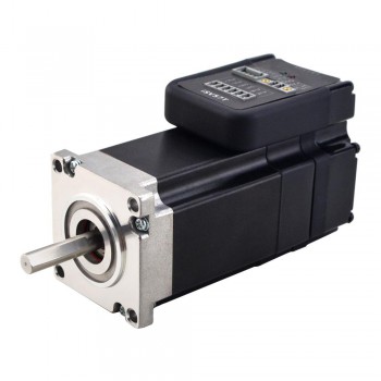
1.Basic understanding of closed-loop stepper motors
A closed-loop stepper motor is a motor that achieves closed-loop control by adding an encoder structure. This motor not only has all the functional characteristics of a stepper motor, but also implements a feedback mechanism in motion control, thereby improving the accuracy and stability of motion. Closed-loop stepper motors achieve real-time monitoring and feedback control of motor position by adding an encoder structure to the motor. This feedback mechanism allows the system to make corrections based on the difference between the actual motion results and the target requirements, thereby improving the accuracy and stability of motion. Compared with open-loop controlled stepper motors, closed-loop stepper motors have significantly improved accuracy, stability, and response speed.
2.Working characteristics of closed-loop stepper motors
1.High-precision positioning: Through real-time feedback from the position sensor, the closed-loop stepper motor can accurately control the rotation of the motor, avoiding the problem of lost steps that may occur in traditional open-loop stepper motors and ensuring the accuracy of positioning.
2.Reduce vibration and noise: The closed-loop stepper motor can better control the torque and speed of the motor during operation, reducing vibration and noise, making the motor run more smoothly.
3.Improve operation stability: The introduction of the closed-loop control system makes the acceleration and deceleration response time of the stepper motor shorter, and the position response is almost synchronized with the input command, which is suitable for occasions that require rapid start and stop.
4.Enhance control flexibility: The closed-loop stepper motor can adjust the control parameters through software to adapt to different application requirements, without complex mechanical adjustments, and is more convenient to use.
3.Methods for increasing the speed of closed-loop stepper motors
1.Change the number of pole pairs: By changing the number of pole pairs of the motor, the speed of the motor can be changed while keeping the torque unchanged. This method is efficient and has a simple control circuit, but the speed regulation range is limited.
2.Variable frequency speed regulation: Variable frequency speed regulation can provide a wide range of speed regulation, and is suitable for low-load operation occasions, which can achieve the purpose of saving power and protecting the motor. However, this method is technically complex and costly.
3.Commutator motor speed regulation: It combines the simple structure of AC synchronous motor and the good speed regulation performance of DC motor, and is suitable for starting and speed regulation of high-speed and large-capacity synchronous motors. But the overload capacity is low.
4.Stator voltage regulation speed regulation: The circuit is simple, the device is small in size, and the price is cheap, but the slip loss is increased during the speed regulation process, the efficiency is low, and the speed regulation range is small.
5.Rotor series resistance speed regulation: The technical requirements are low and the equipment cost is low, but the additional slip power during the speed regulation process is all converted into heat energy loss, and the efficiency is low.
6.Electromagnetic slip clutch speed regulation: The structure is simple, the control device capacity is small, and the operation is reliable, but the speed loss is large and the efficiency is low.
4.Reasons for closed-loop stepper motor loss of steps
1.Load and torque imbalance: When the load is too heavy or the torque is insufficient, the stepper motor cannot provide enough torque to drive the load, resulting in loss of steps. In addition, if the control pulse frequency is too high or too low, it may also cause the stepper motor to lose steps.
2.Unstable power supply voltage: Fluctuation of power supply voltage will affect the running stability of stepper motor and cause lost steps.
3.Control signal interference: The driving mode of stepper motor is usually pulse control. If the control signal is interfered, it may cause stepper motor to lose steps.
4.Rotor acceleration is slower than rotating magnetic field: When the rotor acceleration of stepper motor is slower than rotating magnetic field, stepper motor may lose steps. This is because the input power of motor is insufficient and synchronous torque cannot make the rotor speed follow the rotation speed of stator magnetic field.
5.Inertia of stepper motor and its load: Due to the inertia of stepper motor itself and its load, the motor cannot start and stop immediately during operation, causing lost steps.
6.System resonance: If the frequency of control pulse is equal to the natural frequency of stepper motor, resonance will occur, causing stepper motor to lose steps.
7.Driver or controller interference: Signal interference of driver or controller may cause malfunction, thus causing stepper motor to lose steps.
8.The signal of the driver and the controller does not match: The signal bandwidth mismatch may cause the driver to miss pulses and cause the motor to lose steps.
1.Estructura del motor paso a paso híbrido
La estructura del motor paso a paso híbrido se compone principalmente de dos partes: el estator y el rotor. El estator generalmente tiene 8 polos o 4 polos, y una cierta cantidad de dientes pequeños están distribuidos uniformemente en la superficie del polo. Las bobinas de los polos se pueden energizar en dos direcciones para formar una fase A y una fase B. El rotor se compone de dos engranajes. Un cierto número de dientes pequeños están distribuidos uniformemente alrededor de la circunferencia de estos engranajes, y los dos engranajes están separados entre sí por medio paso de diente. Un imán permanente anular magnetizado axialmente está intercalado entre los dos engranajes. Esta estructura permite que todos los dientes del mismo segmento de palas de rotor tengan la misma polaridad, mientras que dos segmentos de rotor de diferentes segmentos tienen polaridades opuestas. Este diseño combina las ventajas de los motores paso a paso reactivos y los motores paso a paso de imán permanente. Puede lograr un control fino del ángulo de paso y aumentar el par a través de imanes permanentes, lo que muestra ventajas en muchas aplicaciones.
2.Concepto y método de cálculo del ángulo de paso del motor paso a paso híbrido
El ángulo de paso se define como el ángulo de cada paso del motor. En los motores paso a paso híbridos, el ángulo de paso es generalmente de 1,8 grados o 0,9 grados. Entre ellos, el ángulo de paso de 1,8 grados es el más utilizado porque tiene mayor precisión y mejor rendimiento de suavizado. En aplicaciones prácticas, es necesario seleccionar un ángulo de paso adecuado en función de las características del motor y del controlador. El ángulo de paso se calcula de la siguiente manera: ángulo de paso = 360 grados ÷ el número de pasos del motor paso a paso. Por ejemplo, un motor de 200 pasos tiene un ángulo de paso de 1,8 grados y su ángulo de rotación por paso es 1,8 grados ÷ 200 = 0,009 grados.
3.Método de control del motor paso a paso híbrido
1.El control de los motores paso a paso híbridos se logra principalmente cambiando la secuencia de fases, es decir, cambiando la dirección actual del devanado del estator, cambiando así la posición de los polos magnéticos en el rotor, controlando así el ángulo y la dirección de rotación del motor. . Este método de control hace que el motor paso a paso híbrido tenga las características de alta precisión de ángulo de paso, gran par, fuerte anti-disturbios y funcionamiento suave. Es ampliamente utilizado en máquinas herramienta CNC, equipos de automatización, equipos textiles, equipos de impresión, equipos médicos y. otros campos.
2.La conducción subdividida es otro método de control importante. De esta manera, el ángulo de paso real se puede reducir sin cambiar la estructura del motor, mejorando así la precisión del control. El principio de conducción por subdivisión es lograr una operación más precisa en el control haciendo que el ángulo girado en un paso se convierta en 1/n del propio ángulo de paso del motor. Por ejemplo, en el caso de la doble subdivisión, al ajustar la dirección y el tamaño de la corriente, la dirección del campo magnético generado por el devanado A y el devanado B no es directamente de /a a b, sino en algún punto intermedio, logrando así la ángulo de paso real. Se convierte en la mitad del valor original.
4.Fallas comunes y soluciones de los motores paso a paso híbridos
1.El motor paso a paso híbrido no puede funcionar: si el motor paso a paso híbrido se sacude y no puede funcionar después del arranque, primero debe verificar si hay errores en los devanados y las conexiones de accionamiento del motor paso a paso. Si el cableado es correcto, la frecuencia de entrada CP puede ser demasiado alta o el diseño de aumento y disminución de frecuencia no es razonable. En este momento, verifique si el controlador del motor paso a paso está quemado.
2.El motor paso a paso híbrido emite un sonido más alto cuando está en funcionamiento: si el motor paso a paso híbrido puede funcionar normalmente a bajas velocidades, pero no puede arrancar y produce ruido al exceder una cierta velocidad, esto puede deberse a que la frecuencia del pulso excede la frecuencia de arranque del motor paso a paso. Cuando hay carga, la frecuencia de arranque debe ser menor. Para que el motor paso a paso funcione a alta velocidad, se debe adoptar el proceso de aceleración de frecuencia de pulso, es decir, la frecuencia de arranque es baja y luego aumentar gradualmente hasta la alta frecuencia ideal.
3.El motor paso a paso híbrido tiene mucha vibración y ruido: esta situación suele deberse a que el motor paso a paso funciona en la zona de oscilación. Las soluciones incluyen cambiar la frecuencia de la señal de entrada CP para evitar el área de oscilación o usar un controlador de subdivisión para reducir el ángulo de paso y funcionar con mayor suavidad.
4.El motor paso a paso híbrido no funciona después de encenderlo: Las posibles razones incluyen sobrecarga y calado (el motor emite un silbido en este momento), el motor está fuera de línea, si el sistema de control proporciona una señal de pulso al controlador del motor paso a paso. y el cableado. ¿Hay algún problema?
5.El motor paso a paso híbrido tiembla y no puede funcionar continuamente: primero verifique si el devanado del motor y el controlador están conectados correctamente, luego verifique si la frecuencia de la señal del pulso de entrada es demasiado alta y si el diseño de aumento y disminución de frecuencia es razonable.
6.Seleccione la fuente de alimentación y el voltaje adecuados: determine el voltaje de la fuente de alimentación y la corriente de funcionamiento del controlador, seleccione el tipo de fuente de alimentación adecuado (fuente de alimentación lineal o fuente de alimentación conmutada) y determine la corriente de la fuente de alimentación de acuerdo con la corriente de la fase de salida. Yo del conductor. La selección del voltaje de la fuente de alimentación generalmente se determina en función de la velocidad de funcionamiento y los requisitos de respuesta del motor.
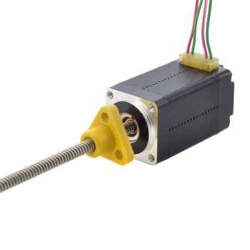
1.A brief introduction to linear stepper motors
Linear stepper motors are a special type of stepper motor, and their design and working principle are different from those of traditional rotary stepper motors. Linear stepper motors are linear motors that achieve linear displacement through linear motion, rather than the rotary motion achieved by traditional stepper motors. This motor converts rotary motion into linear motion through the interaction of the pulsed electromagnetic field generated by the magnetic rotor core and the stator. Linear stepper motors can directly perform linear motion or linear reciprocating motion. If they are converted to linear motion with a rotary motor as the power source, they require the help of gears, cam structures, belts or steel wires and other mechanisms. The introduction of linear stepper motors has greatly simplified the design, making it possible to use linear stepper motors directly for precise linear motion in many applications without installing external mechanical linkage devices.
2.Selection requirements for linear stepper motors
1.Load requirements: First, it is necessary to determine the load that the linear stepper motor needs to bear, including the mass, inertia and friction of the load. Make sure that the selected motor has enough power to drive the load.
2.Linear motion distance: Determine the required linear motion distance so that you can select a linear stepper motor with the appropriate stroke length.
3.Speed requirements: Determine the required linear motion speed. Different models of linear stepper motors have different maximum speeds. Make sure the selected motor can meet the speed requirements.
4.Accuracy and resolution: If high-precision linear motion control is required, consider the resolution and accuracy of the motor. Some linear stepper motors support microstepping operation, providing higher resolution.
5.Environmental conditions: Consider the temperature, humidity, and other conditions of the operating environment to ensure that the selected motor can operate reliably under these conditions.
6.Power supply and voltage: Determine the available power supply type and voltage level to select a linear stepper motor that matches it.
7.Controller and drive: Linear stepper motors usually need to be used in conjunction with controllers and drives to achieve precise position and speed control. Make sure these additional components are considered in the selection.
8.Cost and budget: Select the appropriate linear stepper motor based on the project budget. The prices of motors of different models and specifications can vary greatly.
9.Technical support and service: Make sure that the selected motor supplier provides adequate technical support and after-sales service so that you can get help and repairs when needed.
3.Control methods of linear stepper motors
1.Single-phase excitation control: This is one of the simplest control methods for stepper motors. By activating the coils of each phase in turn, the motor rotates according to a fixed step length. Although this control method is simple, it has poor stability and is suitable for occasions where the control accuracy is not high.
2.Two-phase orthogonal control: The orthogonal control method of two-phase current is adopted. By activating the two-phase windings at the same time, a stable electromagnetic torque is generated to make the motor rotate in a predetermined direction. This control method improves the stability and accuracy of the stepper motor and is suitable for application scenarios with high position requirements.
3.Microstepping control: Each step of the stepper motor is subdivided into multiple microsteps. By accurately controlling the current and time of the stator winding, the motor can move accurately within a small angle range. Microstepping control increases the control complexity, but can obtain smoother movement and higher resolution.
4.Vector control mode: The motor is rotated by controlling the current and voltage of the motor. By adjusting the current size and phase of the stator winding, the motor torque and speed can be precisely controlled. This control mode is suitable for occasions with high requirements on motor performance.
5.Closed-loop control mode: It is a feedback control mode. It monitors the rotation state of the motor in real time and adjusts the control signal according to the monitoring results to achieve precise control of the motor rotation. The closed-loop control mode can greatly improve the control accuracy and stability of the motor and is suitable for occasions with extremely high control accuracy requirements.
6.Pulse direction control mode: The motor rotation is controlled by controlling the pulse and direction signals of the motor. This method is simple and practical and suitable for some simple application scenarios.
4.Advantages of linear stepper motors
1.High-speed responsiveness: Since some mechanical transmission parts with large response time constants, such as lead screws, are eliminated in the system, the dynamic response performance of the entire closed-loop control system is greatly improved, and the response is extremely sensitive and fast.
2.High precision: The mechanical transmission mechanism such as the lead screw is eliminated, and the tracking error caused by the lag of the transmission system during interpolation is reduced. Through linear position detection feedback control, the positioning accuracy of the machine tool can be greatly improved.
3.High transmission stiffness and stable thrust: "Direct drive" improves its transmission stiffness. At the same time, the layout of the linear motor can be arranged according to the surface structure of the machine tool guide rail and the force conditions when the worktable moves. It is usually designed to be evenly distributed and symmetrical to make its movement thrust stable.
4.Fast speed and short acceleration and deceleration process: Linear motors were originally used mainly for maglev trains, and are now used in machine tool feed drives to meet the maximum feed speed of ultra-high-speed cutting. Due to the high-speed responsiveness of "zero transmission", the acceleration and deceleration process is greatly shortened.
5.Unlimited stroke length: By connecting the fixed parts of the linear stepper motor in series on the guide rail, the stroke length of the moving part can be infinitely extended.
6.Low noise during operation: Since the mechanical friction of the transmission screw and other components is eliminated, and the guide pair can use rolling guides or magnetic pad suspension guides (no mechanical contact), the movement noise is greatly reduced.
7.High efficiency: There is no intermediate transmission link, which eliminates the energy loss during mechanical friction.
These advantages make linear stepper motors play an important role in automation equipment, CNC machine tools, precision instruments, 3D printers, laser cutting machines and other fields, especially in applications that require high-performance linear motion control.
1.Introduction
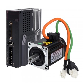
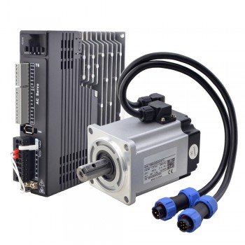
As the core driving component in the field of modern industrial automation, servo motors are widely used in various high-precision and high-performance control systems. According to different power supply methods, servo motors can be mainly divided into two categories: AC Servo Motor and DC Servo Motor. There are significant differences between the two in terms of working principles, control methods, application fields and performance characteristics. This article will discuss and compare the differences between AC servo motors and DC servo motors in detail.
2.Working principle
AC servo motor
AC servo motors are powered by AC power and their working principle is based on the law of electromagnetic induction. When voltage is applied to the stator winding, the servo motor will soon start rotating. The current flowing into the excitation winding and control winding generates a rotating magnetic field in the motor, and the direction of the rotating magnetic field determines the direction of the motor. When the voltage applied to any winding is reversed, the direction of the rotating magnetic field changes, and the direction of the motor also changes. AC servo motors usually include induction servo motors and permanent magnet synchronous servo motors.
DC servo motor
DC servo motors are powered by DC power and their working principle is based on the law of electromagnetic force. The DC servo motor achieves torque output through the interaction of DC current between the stator coil and the rotor coil, and its speed can be adjusted by the voltage. DC servo motors include two types: DC brush servo motors and DC brushless servo motors. Brush DC servo motors have low cost, simple structure, large starting torque, and wide speed range, but have high maintenance costs and are prone to electromagnetic interference; brushless DC servo motors have small size, light weight, large output, and fast response. , high efficiency and other advantages, suitable for various environments.
3.Control method
AC servo motor
AC servo motors usually use closed-loop control systems, which include position feedback sensors (such as encoders) and controllers. The controller realizes closed-loop control by reading the encoder signal and comparing it with the preset target position to adjust the movement of the motor. This control method makes the AC servo motor have the characteristics of high precision, high response speed and high stability.
DC servo motor
DC servo motors can use open-loop control or closed-loop control. In open-loop control, the motor speed is adjusted according to the size and polarity of the input signal. In closed-loop control, the motor performs position control through the position feedback signal returned by the encoder. The control method of DC servo motor is relatively flexible and can be selected according to specific needs.
4.Application areas
AC servo motor
AC servo motors are widely used in industrial automation, machine tools, printing, textiles, robots and other fields. Its high-speed response and high power density make it suitable for high-precision and high-performance applications. For example, in CNC machine tools, AC servo motors can achieve high-speed, high-precision positioning and cutting; in the field of robots, AC servo motors are used to achieve precise control and flexible movement of robots.
DC servo motor
DC servo motors are widely used in robotics, medical equipment, aerospace and other fields. DC servo motors have good speed and position control performance and are widely used in applications requiring precise control and response speed. For example, in medical equipment, DC servo motors are used to achieve precise surgical operations and patient monitoring; in the aerospace field, DC servo motors are used to achieve precise control and navigation of aircraft.
5.Performance characteristics
AC servo motor
AC servo motors have the characteristics of high precision, high response speed, and high stability. Its multi-phase pole form enables the motor to have better torque smoothness and operating stability. In addition, the manufacturing cost of AC servo motors is relatively low, and there are many manufacturers, so the price is relatively cheap.
DC servo motor
DC servo motors have the characteristics of high precision, high response speed, and good dynamic performance. Among them, the brushless DC servo motor also has the advantages of small size, light weight, large output, fast response, and high efficiency. However, the manufacturing technology and maintenance costs of DC servo motors are relatively high, and they are easily affected by external factors such as temperature and voltage.
6.Summary
There are significant differences between AC servo motors and DC servo motors in terms of working principles, control methods, application fields, and performance characteristics. Selecting the type of servo motor suitable for a specific application depends on the specific application requirements and performance specifications. In practical applications, it is necessary to select the appropriate servo motor type according to specific needs and conditions to achieve the best control effect and economic benefits.
Source:https://www.storeboard.com/blogs/electronics/ac-servo-motor-vs-dc-servo-motor/5853599
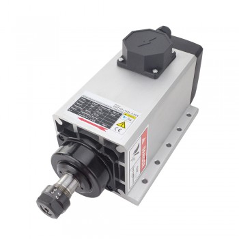
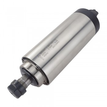
1.Definition of air-cooled spindle motor
An air-cooled spindle motor is a motor that uses air as a cooling medium. Its main feature is to use air flowing through the inside or outside of the motor to reduce the temperature of the motor. This cooling method is usually suitable for application scenarios that do not require excessive cooling or are more cost-sensitive
2.Working principle of air-cooled spindle motor
It mainly relies on air cooling technology, which is a method of cooling the motor through an external fan or blower. Specifically, air cooling technology installs a cooling fan on the motor shaft. When the motor is working, the fan rotates at the same time, and the generated air flow passes through the motor and takes the heat generated by the motor out of the motor through the heat pipe, thereby achieving the purpose of cooling the motor. In addition, a radiator air inlet is set at the front end of the motor, and the air flow generated by the fan is diffused to the surrounding of the motor, further enhancing the cooling effect. This cooling method does not require the motor to rely on its own methods to achieve the cooling effect, but is achieved by adding an external fan or blower. The advantages of air cooling technology include relatively economical price, easy installation, and good cooling effect, so it is widely used in real applications.
The air-cooled spindle motor is usually an AC motor, whose stator runs through three-phase AC, and the rotor is a permanent magnet. A significant advantage of this motor is that it can provide AC energy through a DC power supply, realize precise control of the motor, and solve the life problem caused by the brush. The spindle motor generally uses a photoelectric encoder to detect the speed and rotor position. The detected signal can be used as a feedback signal for vector frequency conversion control and used for magnetic field oriented control to further improve the productivity of machine tools and the utilization rate of tools.
3.The main advantages of air-cooled spindle motors
1.High speed stability: Air-cooled high-speed motors have good speed hardness characteristics and have high speed stability under load fluctuations, which significantly improves the surface finish of the workpiece.
2.Direct drive without transmission error: Air-cooled electric spindles can achieve direct drive without any transmission error, which improves processing accuracy and efficiency.
3.Good axial stability: The rotor of the air-cooled electric spindle is a rare earth permanent magnet structure, with no excitation current, low rotor heat generation, good spindle axial stability, and high workpiece processing accuracy. 4.Flexible power matching: The power can be arbitrarily matched with the thickness and length of the spindle, and the structure is extremely flexible, which can meet the application of various occasions with radial space restrictions on the spindle.
5.Significant energy-saving effect: Under the same power conditions, the energy-saving effect of the air-cooled high-speed motor is 20%~50% higher than that of other asynchronous spindle motors. The greater the power, the more significant the energy-saving effect.
4.Design basis of air-cooled spindle motors
1.The design of air-cooled spindle motors first focuses on the stability and durability of the mechanical structure. Its casing adopts a single seamless structure extruded from high-strength aluminum alloy. This design not only reduces the weight, but also improves the rigidity of the structure. In addition, the casing is also made through special heat treatment to ensure its stability and durability at high speeds.
2.In terms of bearings, the air-cooled spindle motor uses precision radial thrust rolling bearings, which contain steel balls and ceramic balls inside, and can withstand large loads and maintain high precision. In order to keep the bearings running well, high-speed special grease is used for lubrication to reduce friction and increase the service life of the bearings.
3.The design of the air-cooled spindle motor also focuses on heat dissipation performance. By adopting an efficient air cooling system, using fans or forced convection, the heat generated during the operation of the motor is quickly dissipated, keeping the motor running within a safe operating temperature range to avoid damage due to overheating.
4.In addition, the design of the air-cooled spindle motor also takes into account the wide range of product applications, including automatic tool change electric spindles, manual tool change electric spindles, five-axis heads, right-angle heads used with electric spindles, independent drilling and multi-axis electric spindle combinations, etc., to meet the needs of different industries and equipment.
With the development of science and technology, air-cooled spindle motors have also shown a significant development trend in intelligence and remote monitoring. By integrating sensors, data analysis and artificial intelligence algorithms, the operating status of the bearing can be monitored and evaluated in real time, the fault location can be accurately located, and a scientific basis can be provided for maintenance decisions.
1.What is a linear stepper motor
A linear stepper motor is a special type of stepper motor, and its design and working principle are different from traditional rotary stepper motors. A linear stepper motor is a linear motor that achieves linear displacement through linear motion, rather than the rotational motion achieved by traditional stepper motors.
2.Working principle
The construction of a linear stepper motor usually consists of a fixed stator and a movable slider. The stator is equipped with coils inside, and the slider is equipped with permanent magnets. When current passes through the stator coil, a magnetic field is generated. The permanent magnets on the slider interact with the magnetic field of the stator to generate an attractive or repulsive force, which causes the slider to produce linear motion on the fixed axis.
3.Control method
The control of a linear stepper motor involves multiple components, including a transistor bridge, a pre-driver, and a microcontroller unit (MCU). The transistor bridge is responsible for physically controlling the electrical connection of the motor coil, and the pre-driver is controlled by the MCU to provide the required voltage and current. MCU is responsible for generating specific signals to obtain the required motor behavior
4.Advantages of linear stepper motors (compared to traditional stepper motors)
1.High-speed responsiveness
Generally speaking, the dynamic response time of mechanical transmission parts is several orders of magnitude greater than that of electrical components. Since some mechanical transmission parts with large response time constants such as lead screws are eliminated in the system, the dynamic response performance of the entire closed-loop control system is greatly improved, making the response extremely sensitive and fast.
2.High precision
Since the mechanical transmission mechanism such as lead screws is eliminated, the tracking error caused by the lag of the transmission system during interpolation is reduced. Through linear position detection feedback control, the positioning accuracy of the machine tool can be greatly improved.
3.High transmission stiffness and stable thrust
"Direct drive" improves its transmission stiffness. At the same time, the layout of the linear motor can be arranged according to the surface structure of the machine tool guide rail and the force conditions when the worktable moves. It is usually designed to be evenly distributed and symmetrical to make its movement thrust stable.
4.Fast speed, short acceleration and deceleration process
Linear motors were originally used in maglev trains (with a speed of up to 500km/h). Now they are used in machine tool feed drives. Of course, it is no problem to meet the maximum feed speed of ultra-high-speed cutting (required to reach 60~100m/min or higher). Due to the high-speed responsiveness of "zero transmission", the acceleration and deceleration process is greatly shortened, so that high speed can be reached instantly at startup, and it can stop instantly during high-speed operation. The acceleration can generally reach 2~10g (g=9.8m/s2).
5.Unlimited stroke length
By connecting the fixed part of the linear stepper motor in series on the guide rail, the stroke length of the moving part can be extended infinitely.
6.Low noise during operation
Since the mechanical friction of the transmission screw and other components is eliminated, and the guide rail pair can use rolling guide rails or magnetic pad suspension guide rails (no mechanical contact), the movement noise is greatly reduced.
A servo motor is a motor that can precisely control position, speed, and acceleration. It consists of a motor and an attached feedback device that can adjust the motor's input signal based on the feedback information so that the motor can be precisely controlled according to a predetermined motion trajectory.
Servo motors usually use a closed-loop control system, in which a feedback device (such as an encoder or sensor) converts the actual motion state of the motor into an electrical signal and feeds the signal back to the controller. The controller adjusts the motor's input signal based on the difference between the feedback signal and the desired motion state to achieve precise control.

Servo motor test:
1.Connection settings: Connect the servo motor to the test system, ensuring that the power supply, signal lines, and sensors are correctly connected. Follow the instructions of the motor and test system to make the correct connection settings.
2.Calibration and configuration: For newly installed servo motors, calibration and configuration are required. This includes setting motor parameters, limit switches, encoder resolution, etc. Perform calibration and configuration operations as required according to the instructions of the motor and test system.
3.Speed control test: First, perform a speed control test. By giving a target speed, the test system will control the servo motor to reach the target speed and record the actual speed. Tests can be performed under different load conditions to evaluate the speed control performance of the servo motor under different loads.
4.Position control test: Perform a position control test. By giving a target position, the test system will control the servo motor to reach the target position and record the actual position. The position control accuracy and stability under different loads and motion trajectories can be tested.
5.Torque control test: Perform a torque control test. By giving a target torque or torque, the test system will control the servo motor to reach the target torque and record the actual torque. The torque control performance under different load and speed conditions can be tested.

6.Frequency response test: Test the frequency response characteristics of the servo motor by inputting signals of different frequencies. By checking the output response of the servo motor under different frequency inputs, its dynamic response capability and stability can be evaluated.
7.Fault simulation test: Test the fault protection and self-recovery capabilities of the servo motor by simulating faults such as overload and voltage fluctuations. The behavior and reaction of the servo motor under fault conditions can be observed.
8.Data analysis and reporting: Analyze and process the test data to generate test reports and curve graphs. Evaluate the performance and reliability of the servo motor based on the test results, and provide improvement suggestions and maintenance guidance.
Servo motors are often used in applications that require precise positioning and speed control, such as robots, CNC machining, automation equipment, etc. They have the characteristics of fast response, high precision and stability, and can provide reliable motion control under various working conditions.
When performing the above tests, adjustments and optimizations need to be made according to the specific test requirements and motor types, while ensuring the implementation of safety measures to avoid possible dangers and damage.
Source:https://www.storeboard.com/blogs/ecommerce/how-to-test-a-servo-motor/5824708
1.Brief description of the working principle of servo motor
Servo motor is a high-performance and high-precision motor widely used in the field of industrial automation. Its main feature is that it can accurately control the output torque and angle according to the command signal, and it has the advantages of fast response, high precision and strong stability.
The control system of servo motor is generally composed of power supply, controller, encoder, driver and motor. Among them, the driver is the core part of the servo motor control system. It controls the speed and direction of the motor by controlling the magnitude and direction of the current to achieve precise control.
2.Speed regulation method of servo motor
1.Voltage speed regulation method: speed regulation is achieved by changing the voltage at both ends of the motor. This method has a simple structure and is easy to implement, but the efficiency is low and the control accuracy is relatively low.
2.Current speed regulation method: speed regulation is achieved by changing the current of the motor. This method has high speed regulation accuracy and fast response speed, but the structure is complex and the cost is high.
3.Pulse width modulation (PWM) speed regulation method: speed regulation is achieved by changing the pulse width of the motor power supply. This method can achieve a wider speed regulation range and high efficiency, but the structure is complex and the cost is high.
4.Field Oriented Control (FOC) Speed Control Method: This is a speed control method based on the principle of vector control, which can achieve high-precision speed and torque control and is suitable for high-performance application scenarios.
5.Pulse counting speed control: Control the speed and position of the motor by sending different numbers of pulse signals to the servo drive, which is suitable for occasions that require precise position control.
6.PID speed control: Control the position and speed of the motor by adjusting the position proportional coefficient, differential coefficient and integral coefficient, which is suitable for applications that require precise speed and position control.
3.Servo Motor Braking Principle
The braking of the servo motor is mainly to stop or keep the motor stationary. The mechanical braking is mainly achieved by mechanical brakes, and the electrical method can be achieved by the following four methods:
1.Direct power-off braking
Direct power-off braking refers to directly cutting off the power supply, so that the motor loses the driving force and stops rotating directly. This method is simple to brake, but it has a greater damage to the motor's back electromotive force and is easy to damage the motor or drive.
2.Reverse power supply braking
Reverse power supply braking refers to braking by reversing the polarity of the power supply. The motor will generate reverse torque, thereby achieving rapid stopping. This method is suitable for occasions where precision is not required.
3.Short-circuit braking
Short-circuit braking refers to directly short-circuiting the two ends of the motor to produce a damping effect on the motor, and the motor torque decreases rapidly, thereby achieving a quick stop. This method causes less damage to the motor and the driver, and has higher precision.
4.Maintaining current braking
Maintaining current braking refers to controlling the current of the driver to make the motor rotate to 0 position and stop. This method has a stable braking effect and causes little damage to the motor and driver. Since the current needs to be controlled, a more precise controller is required.
In summary, the braking of the servo motor can be achieved either mechanically or electrically. Among them, electrical braking is widely used because of its stable braking effect and little damage to the motor and driver.
Source:https://www.storeboard.com/blogs/apps-and-software/braking-principle-of-servo-motor/5815261
The axial force bearing range of stepper motors varies depending on the type and brand, generally between 30N and 500N.
1. The effect of axial force on stepper motors
Before understanding how much axial force a stepper motor can withstand, you first need to understand the impact of axial force on the operation of the stepper motor. Axial force refers to the force generated in the axial direction during the operation of the motor, usually caused by the weight of the load or the inertial force during the movement.

When a stepper motor is subjected to axial force, it is easy to cause deformation and damage to the internal parts of the motor, affecting the movement accuracy and life of the motor.
2. Factors affecting the axial force of stepper motors
The size of the axial force that a stepper motor can withstand is related to its structure, material, processing technology and other factors. The important factors include:
1. Motor type: Different types of stepper motors withstand different ranges of axial force. For example, the axial force borne by Hall effect stepper motors is generally small, while hybrid stepper motors have a greater ability to withstand axial force.
2. Motor size: Generally, larger motors are more able to withstand larger axial forces.
3. Motor materials and processing technology: The quality of materials and processing technology directly affects the motor's ability to withstand axial force. High-quality motor materials and fine processing technology can ensure better bearing capacity of the motor.
3. How much axial force can a stepper motor generally withstand?
The axial force of common stepper motors on the market is between 30N and 500N. However, the specific value still needs to be considered comprehensively based on parameters such as motor type, size, material and processing technology.
In actual use, in order to ensure the normal operation of the motor and extend its service life, excessive axial force should be avoided as much as possible. At the same time, the bearing capacity of the motor can be improved by increasing the number of motor bearings and increasing the inner diameter of the bearings.
4. Summary
This article introduces in detail the relevant concepts and influencing factors of the axial force of the stepper motor, as well as the common bearing capacity range. In practical applications, we need to comprehensively consider the bearing capacity of the stepper motor according to the specific motor type and use environment, and take appropriate protective measures to ensure the normal operation and service life of the motor.
Source:https://www.storeboard.com/blogs/general/how-much-axial-force-can-a-stepper-motor-withstand/5810166