Minnie's blog
1.What is a linear stepper motor
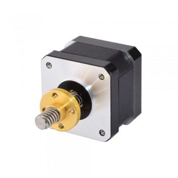
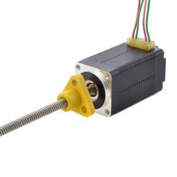
A linear stepper motor is a special type of stepper motor, and its design and working principle are different from traditional rotary stepper motors. A linear stepper motor is a linear motor that achieves linear displacement through linear motion, rather than the rotational motion achieved by traditional stepper motors.
2.Working principle
The construction of a linear stepper motor usually consists of a fixed stator and a movable slider. The stator is equipped with coils inside, and the slider is equipped with permanent magnets. When current passes through the stator coil, a magnetic field is generated. The permanent magnets on the slider interact with the magnetic field of the stator to generate an attractive or repulsive force, which causes the slider to produce linear motion on the fixed axis.
3.Control method
The control of a linear stepper motor involves multiple components, including a transistor bridge, a pre-driver, and a microcontroller unit (MCU). The transistor bridge is responsible for physically controlling the electrical connection of the motor coil, and the pre-driver is controlled by the MCU to provide the required voltage and current. MCU is responsible for generating specific signals to obtain the required motor behavior
4.Advantages of linear stepper motors (compared to traditional stepper motors)
1.High-speed responsiveness
Generally speaking, the dynamic response time of mechanical transmission parts is several orders of magnitude greater than that of electrical components. Since some mechanical transmission parts with large response time constants such as lead screws are eliminated in the system, the dynamic response performance of the entire closed-loop control system is greatly improved, making the response extremely sensitive and fast.
2.High precision
Since the mechanical transmission mechanism such as lead screws is eliminated, the tracking error caused by the lag of the transmission system during interpolation is reduced. Through linear position detection feedback control, the positioning accuracy of the machine tool can be greatly improved.
3.High transmission stiffness and stable thrust
"Direct drive" improves its transmission stiffness. At the same time, the layout of the linear motor can be arranged according to the surface structure of the machine tool guide rail and the force conditions when the worktable moves. It is usually designed to be evenly distributed and symmetrical to make its movement thrust stable.
4.Fast speed, short acceleration and deceleration process
Linear motors were originally used in maglev trains (with a speed of up to 500km/h). Now they are used in machine tool feed drives. Of course, it is no problem to meet the maximum feed speed of ultra-high-speed cutting (required to reach 60~100m/min or higher). Due to the high-speed responsiveness of "zero transmission", the acceleration and deceleration process is greatly shortened, so that high speed can be reached instantly at startup, and it can stop instantly during high-speed operation. The acceleration can generally reach 2~10g (g=9.8m/s2).
5.Unlimited stroke length
By connecting the fixed part of the linear stepper motor in series on the guide rail, the stroke length of the moving part can be extended infinitely.
6.Low noise during operation
Since the mechanical friction of the transmission screw and other components is eliminated, and the guide rail pair can use rolling guide rails or magnetic pad suspension guide rails (no mechanical contact), the movement noise is greatly reduced.
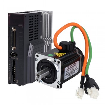
A servo motor is a motor that can precisely control position, speed, and acceleration. It consists of a motor and an attached feedback device that can adjust the motor's input signal based on the feedback information so that the motor can be precisely controlled according to a predetermined motion trajectory.
Servo motors usually use a closed-loop control system, in which a feedback device (such as an encoder or sensor) converts the actual motion state of the motor into an electrical signal and feeds the signal back to the controller. The controller adjusts the motor's input signal based on the difference between the feedback signal and the desired motion state to achieve precise control.

Servo motor test:
1.Connection settings: Connect the servo motor to the test system, ensuring that the power supply, signal lines, and sensors are correctly connected. Follow the instructions of the motor and test system to make the correct connection settings.
2.Calibration and configuration: For newly installed servo motors, calibration and configuration are required. This includes setting motor parameters, limit switches, encoder resolution, etc. Perform calibration and configuration operations as required according to the instructions of the motor and test system.
3.Speed control test: First, perform a speed control test. By giving a target speed, the test system will control the servo motor to reach the target speed and record the actual speed. Tests can be performed under different load conditions to evaluate the speed control performance of the servo motor under different loads.
4.Position control test: Perform a position control test. By giving a target position, the test system will control the servo motor to reach the target position and record the actual position. The position control accuracy and stability under different loads and motion trajectories can be tested.
5.Torque control test: Perform a torque control test. By giving a target torque or torque, the test system will control the servo motor to reach the target torque and record the actual torque. The torque control performance under different load and speed conditions can be tested.

6.Frequency response test: Test the frequency response characteristics of the servo motor by inputting signals of different frequencies. By checking the output response of the servo motor under different frequency inputs, its dynamic response capability and stability can be evaluated.
7.Fault simulation test: Test the fault protection and self-recovery capabilities of the servo motor by simulating faults such as overload and voltage fluctuations. The behavior and reaction of the servo motor under fault conditions can be observed.
8.Data analysis and reporting: Analyze and process the test data to generate test reports and curve graphs. Evaluate the performance and reliability of the servo motor based on the test results, and provide improvement suggestions and maintenance guidance.
Servo motors are often used in applications that require precise positioning and speed control, such as robots, CNC machining, automation equipment, etc. They have the characteristics of fast response, high precision and stability, and can provide reliable motion control under various working conditions.
When performing the above tests, adjustments and optimizations need to be made according to the specific test requirements and motor types, while ensuring the implementation of safety measures to avoid possible dangers and damage.
Source:https://www.storeboard.com/blogs/ecommerce/how-to-test-a-servo-motor/5824708
1.Brief description of the working principle of servo motor
Servo motor is a high-performance and high-precision motor widely used in the field of industrial automation. Its main feature is that it can accurately control the output torque and angle according to the command signal, and it has the advantages of fast response, high precision and strong stability.
The control system of servo motor is generally composed of power supply, controller, encoder, driver and motor. Among them, the driver is the core part of the servo motor control system. It controls the speed and direction of the motor by controlling the magnitude and direction of the current to achieve precise control.
2.Speed regulation method of servo motor
1.Voltage speed regulation method: speed regulation is achieved by changing the voltage at both ends of the motor. This method has a simple structure and is easy to implement, but the efficiency is low and the control accuracy is relatively low.
2.Current speed regulation method: speed regulation is achieved by changing the current of the motor. This method has high speed regulation accuracy and fast response speed, but the structure is complex and the cost is high.
3.Pulse width modulation (PWM) speed regulation method: speed regulation is achieved by changing the pulse width of the motor power supply. This method can achieve a wider speed regulation range and high efficiency, but the structure is complex and the cost is high.
4.Field Oriented Control (FOC) Speed Control Method: This is a speed control method based on the principle of vector control, which can achieve high-precision speed and torque control and is suitable for high-performance application scenarios.
5.Pulse counting speed control: Control the speed and position of the motor by sending different numbers of pulse signals to the servo drive, which is suitable for occasions that require precise position control.
6.PID speed control: Control the position and speed of the motor by adjusting the position proportional coefficient, differential coefficient and integral coefficient, which is suitable for applications that require precise speed and position control.
3.Servo Motor Braking Principle
The braking of the servo motor is mainly to stop or keep the motor stationary. The mechanical braking is mainly achieved by mechanical brakes, and the electrical method can be achieved by the following four methods:
1.Direct power-off braking
Direct power-off braking refers to directly cutting off the power supply, so that the motor loses the driving force and stops rotating directly. This method is simple to brake, but it has a greater damage to the motor's back electromotive force and is easy to damage the motor or drive.
2.Reverse power supply braking
Reverse power supply braking refers to braking by reversing the polarity of the power supply. The motor will generate reverse torque, thereby achieving rapid stopping. This method is suitable for occasions where precision is not required.
3.Short-circuit braking
Short-circuit braking refers to directly short-circuiting the two ends of the motor to produce a damping effect on the motor, and the motor torque decreases rapidly, thereby achieving a quick stop. This method causes less damage to the motor and the driver, and has higher precision.
4.Maintaining current braking
Maintaining current braking refers to controlling the current of the driver to make the motor rotate to 0 position and stop. This method has a stable braking effect and causes little damage to the motor and driver. Since the current needs to be controlled, a more precise controller is required.
In summary, the braking of the servo motor can be achieved either mechanically or electrically. Among them, electrical braking is widely used because of its stable braking effect and little damage to the motor and driver.
Source:https://www.storeboard.com/blogs/apps-and-software/braking-principle-of-servo-motor/5815261
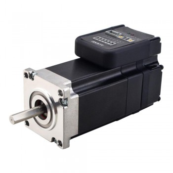
The axial force bearing range of stepper motors varies depending on the type and brand, generally between 30N and 500N.
1. The effect of axial force on stepper motors
Before understanding how much axial force a stepper motor can withstand, you first need to understand the impact of axial force on the operation of the stepper motor. Axial force refers to the force generated in the axial direction during the operation of the motor, usually caused by the weight of the load or the inertial force during the movement.
When a stepper motor is subjected to axial force, it is easy to cause deformation and damage to the internal parts of the motor, affecting the movement accuracy and life of the motor.
2. Factors affecting the axial force of stepper motors
The size of the axial force that a stepper motor can withstand is related to its structure, material, processing technology and other factors. The important factors include:
1. Motor type: Different types of stepper motors withstand different ranges of axial force. For example, the axial force borne by Hall effect stepper motors is generally small, while hybrid stepper motors have a greater ability to withstand axial force.
2. Motor size: Generally, larger motors are more able to withstand larger axial forces.
3. Motor materials and processing technology: The quality of materials and processing technology directly affects the motor's ability to withstand axial force. High-quality motor materials and fine processing technology can ensure better bearing capacity of the motor.
3. How much axial force can a stepper motor generally withstand?
The axial force of common stepper motors on the market is between 30N and 500N. However, the specific value still needs to be considered comprehensively based on parameters such as motor type, size, material and processing technology.
In actual use, in order to ensure the normal operation of the motor and extend its service life, excessive axial force should be avoided as much as possible. At the same time, the bearing capacity of the motor can be improved by increasing the number of motor bearings and increasing the inner diameter of the bearings.
4. Summary
This article introduces in detail the relevant concepts and influencing factors of the axial force of the stepper motor, as well as the common bearing capacity range. In practical applications, we need to comprehensively consider the bearing capacity of the stepper motor according to the specific motor type and use environment, and take appropriate protective measures to ensure the normal operation and service life of the motor.
Source:https://www.storeboard.com/blogs/general/how-much-axial-force-can-a-stepper-motor-withstand/5810166