Minnie's blog
1.Estructura del motor paso a paso híbrido
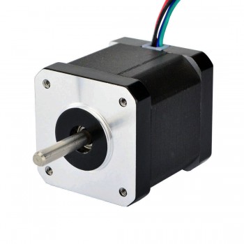
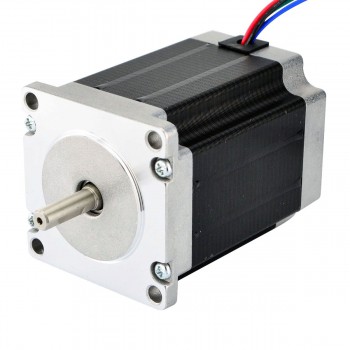
La estructura del motor paso a paso híbrido se compone principalmente de dos partes: el estator y el rotor. El estator generalmente tiene 8 polos o 4 polos, y una cierta cantidad de dientes pequeños están distribuidos uniformemente en la superficie del polo. Las bobinas de los polos se pueden energizar en dos direcciones para formar una fase A y una fase B. El rotor se compone de dos engranajes. Un cierto número de dientes pequeños están distribuidos uniformemente alrededor de la circunferencia de estos engranajes, y los dos engranajes están separados entre sí por medio paso de diente. Un imán permanente anular magnetizado axialmente está intercalado entre los dos engranajes. Esta estructura permite que todos los dientes del mismo segmento de palas de rotor tengan la misma polaridad, mientras que dos segmentos de rotor de diferentes segmentos tienen polaridades opuestas. Este diseño combina las ventajas de los motores paso a paso reactivos y los motores paso a paso de imán permanente. Puede lograr un control fino del ángulo de paso y aumentar el par a través de imanes permanentes, lo que muestra ventajas en muchas aplicaciones.
2.Concepto y método de cálculo del ángulo de paso del motor paso a paso híbrido
El ángulo de paso se define como el ángulo de cada paso del motor. En los motores paso a paso híbridos, el ángulo de paso es generalmente de 1,8 grados o 0,9 grados. Entre ellos, el ángulo de paso de 1,8 grados es el más utilizado porque tiene mayor precisión y mejor rendimiento de suavizado. En aplicaciones prácticas, es necesario seleccionar un ángulo de paso adecuado en función de las características del motor y del controlador. El ángulo de paso se calcula de la siguiente manera: ángulo de paso = 360 grados ÷ el número de pasos del motor paso a paso. Por ejemplo, un motor de 200 pasos tiene un ángulo de paso de 1,8 grados y su ángulo de rotación por paso es 1,8 grados ÷ 200 = 0,009 grados.
3.Método de control del motor paso a paso híbrido
1.El control de los motores paso a paso híbridos se logra principalmente cambiando la secuencia de fases, es decir, cambiando la dirección actual del devanado del estator, cambiando así la posición de los polos magnéticos en el rotor, controlando así el ángulo y la dirección de rotación del motor. . Este método de control hace que el motor paso a paso híbrido tenga las características de alta precisión de ángulo de paso, gran par, fuerte anti-disturbios y funcionamiento suave. Es ampliamente utilizado en máquinas herramienta CNC, equipos de automatización, equipos textiles, equipos de impresión, equipos médicos y. otros campos.
2.La conducción subdividida es otro método de control importante. De esta manera, el ángulo de paso real se puede reducir sin cambiar la estructura del motor, mejorando así la precisión del control. El principio de conducción por subdivisión es lograr una operación más precisa en el control haciendo que el ángulo girado en un paso se convierta en 1/n del propio ángulo de paso del motor. Por ejemplo, en el caso de la doble subdivisión, al ajustar la dirección y el tamaño de la corriente, la dirección del campo magnético generado por el devanado A y el devanado B no es directamente de /a a b, sino en algún punto intermedio, logrando así la ángulo de paso real. Se convierte en la mitad del valor original.
4.Fallas comunes y soluciones de los motores paso a paso híbridos
1.El motor paso a paso híbrido no puede funcionar: si el motor paso a paso híbrido se sacude y no puede funcionar después del arranque, primero debe verificar si hay errores en los devanados y las conexiones de accionamiento del motor paso a paso. Si el cableado es correcto, la frecuencia de entrada CP puede ser demasiado alta o el diseño de aumento y disminución de frecuencia no es razonable. En este momento, verifique si el controlador del motor paso a paso está quemado.
2.El motor paso a paso híbrido emite un sonido más alto cuando está en funcionamiento: si el motor paso a paso híbrido puede funcionar normalmente a bajas velocidades, pero no puede arrancar y produce ruido al exceder una cierta velocidad, esto puede deberse a que la frecuencia del pulso excede la frecuencia de arranque del motor paso a paso. Cuando hay carga, la frecuencia de arranque debe ser menor. Para que el motor paso a paso funcione a alta velocidad, se debe adoptar el proceso de aceleración de frecuencia de pulso, es decir, la frecuencia de arranque es baja y luego aumentar gradualmente hasta la alta frecuencia ideal.
3.El motor paso a paso híbrido tiene mucha vibración y ruido: esta situación suele deberse a que el motor paso a paso funciona en la zona de oscilación. Las soluciones incluyen cambiar la frecuencia de la señal de entrada CP para evitar el área de oscilación o usar un controlador de subdivisión para reducir el ángulo de paso y funcionar con mayor suavidad.
4.El motor paso a paso híbrido no funciona después de encenderlo: Las posibles razones incluyen sobrecarga y calado (el motor emite un silbido en este momento), el motor está fuera de línea, si el sistema de control proporciona una señal de pulso al controlador del motor paso a paso. y el cableado. ¿Hay algún problema?
5.El motor paso a paso híbrido tiembla y no puede funcionar continuamente: primero verifique si el devanado del motor y el controlador están conectados correctamente, luego verifique si la frecuencia de la señal del pulso de entrada es demasiado alta y si el diseño de aumento y disminución de frecuencia es razonable.
6.Seleccione la fuente de alimentación y el voltaje adecuados: determine el voltaje de la fuente de alimentación y la corriente de funcionamiento del controlador, seleccione el tipo de fuente de alimentación adecuado (fuente de alimentación lineal o fuente de alimentación conmutada) y determine la corriente de la fuente de alimentación de acuerdo con la corriente de la fase de salida. Yo del conductor. La selección del voltaje de la fuente de alimentación generalmente se determina en función de la velocidad de funcionamiento y los requisitos de respuesta del motor.
1.A brief introduction to linear stepper motors
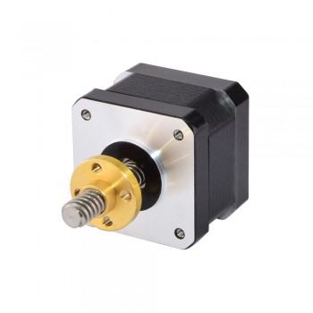
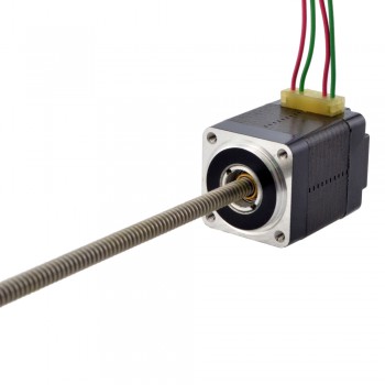
Linear stepper motors are a special type of stepper motor, and their design and working principle are different from those of traditional rotary stepper motors. Linear stepper motors are linear motors that achieve linear displacement through linear motion, rather than the rotary motion achieved by traditional stepper motors. This motor converts rotary motion into linear motion through the interaction of the pulsed electromagnetic field generated by the magnetic rotor core and the stator. Linear stepper motors can directly perform linear motion or linear reciprocating motion. If they are converted to linear motion with a rotary motor as the power source, they require the help of gears, cam structures, belts or steel wires and other mechanisms. The introduction of linear stepper motors has greatly simplified the design, making it possible to use linear stepper motors directly for precise linear motion in many applications without installing external mechanical linkage devices.
2.Selection requirements for linear stepper motors
1.Load requirements: First, it is necessary to determine the load that the linear stepper motor needs to bear, including the mass, inertia and friction of the load. Make sure that the selected motor has enough power to drive the load.
2.Linear motion distance: Determine the required linear motion distance so that you can select a linear stepper motor with the appropriate stroke length.
3.Speed requirements: Determine the required linear motion speed. Different models of linear stepper motors have different maximum speeds. Make sure the selected motor can meet the speed requirements.
4.Accuracy and resolution: If high-precision linear motion control is required, consider the resolution and accuracy of the motor. Some linear stepper motors support microstepping operation, providing higher resolution.
5.Environmental conditions: Consider the temperature, humidity, and other conditions of the operating environment to ensure that the selected motor can operate reliably under these conditions.
6.Power supply and voltage: Determine the available power supply type and voltage level to select a linear stepper motor that matches it.
7.Controller and drive: Linear stepper motors usually need to be used in conjunction with controllers and drives to achieve precise position and speed control. Make sure these additional components are considered in the selection.
8.Cost and budget: Select the appropriate linear stepper motor based on the project budget. The prices of motors of different models and specifications can vary greatly.
9.Technical support and service: Make sure that the selected motor supplier provides adequate technical support and after-sales service so that you can get help and repairs when needed.
3.Control methods of linear stepper motors
1.Single-phase excitation control: This is one of the simplest control methods for stepper motors. By activating the coils of each phase in turn, the motor rotates according to a fixed step length. Although this control method is simple, it has poor stability and is suitable for occasions where the control accuracy is not high.
2.Two-phase orthogonal control: The orthogonal control method of two-phase current is adopted. By activating the two-phase windings at the same time, a stable electromagnetic torque is generated to make the motor rotate in a predetermined direction. This control method improves the stability and accuracy of the stepper motor and is suitable for application scenarios with high position requirements.
3.Microstepping control: Each step of the stepper motor is subdivided into multiple microsteps. By accurately controlling the current and time of the stator winding, the motor can move accurately within a small angle range. Microstepping control increases the control complexity, but can obtain smoother movement and higher resolution.
4.Vector control mode: The motor is rotated by controlling the current and voltage of the motor. By adjusting the current size and phase of the stator winding, the motor torque and speed can be precisely controlled. This control mode is suitable for occasions with high requirements on motor performance.
5.Closed-loop control mode: It is a feedback control mode. It monitors the rotation state of the motor in real time and adjusts the control signal according to the monitoring results to achieve precise control of the motor rotation. The closed-loop control mode can greatly improve the control accuracy and stability of the motor and is suitable for occasions with extremely high control accuracy requirements.
6.Pulse direction control mode: The motor rotation is controlled by controlling the pulse and direction signals of the motor. This method is simple and practical and suitable for some simple application scenarios.
4.Advantages of linear stepper motors
1.High-speed responsiveness: Since some mechanical transmission parts with large response time constants, such as lead screws, are eliminated in the system, the dynamic response performance of the entire closed-loop control system is greatly improved, and the response is extremely sensitive and fast.
2.High precision: The mechanical transmission mechanism such as the lead screw is eliminated, and the tracking error caused by the lag of the transmission system during interpolation is reduced. Through linear position detection feedback control, the positioning accuracy of the machine tool can be greatly improved.
3.High transmission stiffness and stable thrust: "Direct drive" improves its transmission stiffness. At the same time, the layout of the linear motor can be arranged according to the surface structure of the machine tool guide rail and the force conditions when the worktable moves. It is usually designed to be evenly distributed and symmetrical to make its movement thrust stable.
4.Fast speed and short acceleration and deceleration process: Linear motors were originally used mainly for maglev trains, and are now used in machine tool feed drives to meet the maximum feed speed of ultra-high-speed cutting. Due to the high-speed responsiveness of "zero transmission", the acceleration and deceleration process is greatly shortened.
5.Unlimited stroke length: By connecting the fixed parts of the linear stepper motor in series on the guide rail, the stroke length of the moving part can be infinitely extended.
6.Low noise during operation: Since the mechanical friction of the transmission screw and other components is eliminated, and the guide pair can use rolling guides or magnetic pad suspension guides (no mechanical contact), the movement noise is greatly reduced.
7.High efficiency: There is no intermediate transmission link, which eliminates the energy loss during mechanical friction.
These advantages make linear stepper motors play an important role in automation equipment, CNC machine tools, precision instruments, 3D printers, laser cutting machines and other fields, especially in applications that require high-performance linear motion control.