Sirra's blog
1.Working principle of stepper motor encoders
The working principle of stepper motor encoders is to convert electrical pulse signals into corresponding angular displacement or linear displacement. For each input pulse signal, the rotor of the stepper motor will rotate a fixed angle or move forward one step. The output angular displacement or linear displacement is proportional to the number of input pulses, and the speed is proportional to the pulse frequency. The application of encoders in stepper motors is mainly reflected in closed-loop control systems. The encoder can measure the rotation angle and position of the motor and feed this information back to the control system to achieve more precise control.

2.Structural features of stepper motor encoders
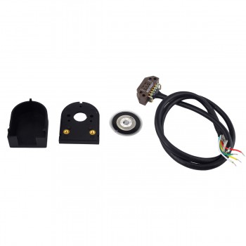
1.Photoelectric encoders: Use photoelectric sensors and encoder disks to measure the position and movement of the rotor. The grating or encoding hole on the encoder disk is sensed by the photoelectric sensor to measure the angle and position of the rotor. This encoder is widely used in stepper servo motor systems that require high-precision position measurement.
2.Magnetic encoders: Use magnetic sensors and magnetic scales to detect the position and movement of the rotor. The interaction between the magnetic strip on the magnetic scale and the magnetic sensor is used to achieve angle and position measurement. Suitable for stepper servo motor systems with certain requirements for accuracy and stability.
3.Grating scale encoder: It uses the interaction between the grating texture on the grating scale and the photoelectric sensor to provide very accurate position measurement. It is often used in stepper servo motor systems with extremely high accuracy requirements.
4.Magnetic scale encoder: A high-precision encoder based on magnetic technology, which uses the interaction between the magnetic texture on the magnetic scale and the magnetic sensor to provide high-precision position measurement. It is particularly suitable for stepper servo motor systems with extremely high requirements for accuracy and stability.
3.Notes on the installation of stepper motor encoders
1.Determination of the installation position: Since the output shaft of the general motor model is shorter, there is basically no more space for the encoder after the pulley is installed. Therefore, it is necessary to determine the installation position to ensure that the plug plays a speed limiting role in future use. If there is no space on the output shaft, it is usually chosen to install the encoder in the second half of the encoder.
2.Opening a hole: After determining the installation position, the next step is to open a hole. Usually, the transition hole on the rear cover of the engine is open. In order to ensure the stable performance of the encoder in future use, a transition shaft must be installed behind the motor to provide support. In addition, an S-shaped steel plate must be used on the motor back cover for double fastening.
3.Install the connector: In order to ensure the stability of the connection between the encoder and the motor, it is necessary to install a plug between the two, one side connected to the motor and the other side connected to the encoder. The choice of connector is not very strict, and ordinary plugs can be used.
4.Inspection: After completing the above steps, it is very necessary to conduct important follow-up inspections. Any small negligence may cause the connection to be unreinforced and loose, thus affecting the later operation of the equipment.

4.Common faults of stepper motor encoders
1.Mechanical failure: The mechanical structure inside the encoder is damaged or excessively worn, causing the components to fail to operate normally. This may be due to loose mechanical installation, external force impact, or wear caused by long-term use.
2.Electrical failure: The internal circuit components of the encoder are damaged or poorly connected, resulting in the inability to transmit signals. This may be due to poor connection, loose wiring, or electromagnetic interference (EMI) affecting signal transmission.
3.Environmental failure: The ambient temperature is too high or too low, and the humidity is too high or too low when the encoder is working, causing the internal components to fail. Environmental factors such as strong electromagnetic fields, high temperatures, high humidity, and vibrations may also interfere with the normal function of the encoder.
4.Signal loss: The signal is interrupted due to poor connection, loose wiring, or failure of the sensor itself. Electromagnetic interference (EMI) may also affect signal transmission, causing signal interruption.
5.Reduced resolution: The resolution of the encoder may be reduced due to internal wear, contamination, or improper use. The optical components of the optical encoder are covered with dust, which may prevent light from passing normally and reduce the resolution.
6.Power supply failure: The power supply voltage is unstable, the connector is loose, or there is a fault in the power supply itself, causing the encoder to fail to operate normally. It is necessary to ensure that the power supply equipment is working properly and use a voltage stabilizer or uninterruptible power supply (UPS) when necessary.
7.Excessive temperature: The internal components of the encoder may overheat when it is in a high temperature environment for a long time, causing electronic components to fail or performance to deteriorate. It is necessary to ensure that the encoder works within the specified temperature range and take cooling measures.
