Vicent's blog
1.What is a closed-loop stepper motor
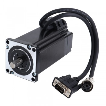
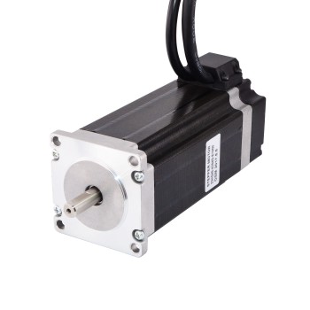
A closed-loop stepper motor is a motor that combines the characteristics of a stepper motor and a servo motor, and achieves high precision and high efficiency through closed-loop control. A closed-loop stepper motor can remain absolutely still when stationary, and will not have slight fluctuations when stopped like a servo motor. Its debugging and use are relatively simple, and only a few potentiometer positions of the driver need to be adjusted, which is suitable for users with low technical requirements.
2.Working principle of closed-loop stepper motors
The working principle of closed-loop stepper motors is to control the rotation of the motor by controlling the change of current, thereby converting electrical energy into mechanical energy. A closed-loop stepper motor is mainly composed of a stator, a rotor, a bearing seat and an encoder. The stator is the fixed part, and the rotor is the rotating part. The encoder is used to detect the position of the rotor and feed the position information back to the controller to form a closed-loop control.
3.Performance advantages of closed-loop stepper motors
1.Improve torque and speed: Closed-loop stepper motors achieve higher accuracy and more stable operation than open-loop control by adding position feedback devices (such as photoelectric encoders or magnetic encoders). It can maintain a large torque when running at high speed, suitable for 0-1500rpm occasions, and can even run to 3000-4000RPM without losing steps.
2.Improve motion accuracy: Closed-loop stepper motors can automatically adjust the winding current through encoder feedback, reduce heat and vibration, and improve motion accuracy. The higher the accuracy of the encoder, the higher the positioning accuracy of the motor. For example, the resolution of a 5000-line encoder can reach 0.018°, which is much higher than the accuracy of an open-loop stepper motor.
3.Reduce vibration and noise: Due to the existence of closed-loop control, the stepper motor can maintain the torque characteristics when stopped, and will not produce micro-vibrations like the servo system, thereby improving the repeated positioning accuracy of the motion system. This makes closed-loop stepper motors perform better in situations where high-precision positioning is required.
4.Adapt to frequent start and stop: Closed-loop stepper motors are suitable for occasions that require frequent start/stop. They can maintain stable positioning under load changes, without gain adjustment, and simplify the debugging process.
5.High response speed: Closed-loop stepper motors run synchronously with control instructions, can complete precise positioning in a short stroke and short time, have fast response speed, and are suitable for precise positioning needs of short strokes.
6.Adapt to large inertia loads: Closed-loop stepper motors can drive larger inertia loads than servo motors of the same installation size, and are suitable for occasions that need to drive large inertia loads.
7.Efficient acceleration and deceleration: Closed-loop stepper motors can be accelerated and decelerated automatically and effectively, reducing the need for manual adjustment and improving the overall efficiency of the system.
4.Operating instructions for closed-loop stepper motors
1.Hardware connection
The hardware connection of the closed-loop stepper motor requires the installation of an encoder. According to the subdivision requirements, encoders with different levels of resolution are used for real-time feedback. The circuit uses ultra-large-scale circuit FPGA, and the input and output can reach the corresponding frequency of mega-level. The power supply is 3.3V. The 2596 switching power supply is used to convert 24V to 3.3V, which is convenient and practical.
2.Origin control
According to the Z signal of the encoder, the coordinate origin is identified and calculated, and the accuracy can reach 2/encoder resolution × 4. In the origin mode, the pulse is output at a frequency synchronized with the input pulse. When the origin switch is touched, the output pulse frequency is reduced. According to the Z signal of the encoder, the coordinate origin is identified and calculated. After returning to the origin, the signal is output. This signal and its data are always maintained without power failure.
3.Out-of-step control
According to the feedback data of the encoder, the output pulse is adjusted in real time, and corresponding measures are taken according to the degree of out-of-step adjustment. In the running mode, the pulse is output at a frequency synchronized with the input pulse, and the feedback data is calculated at the same time. If an error occurs, it is corrected in time.
4.Circuit principle description
The circuit principle description includes the calculation of the input pulse and the feedback pulse after 4 times the frequency orthogonal decoding, and the output pulse quantity and frequency are corrected in time. The circuit has two modes: return to origin mode and running mode. In the origin mode, the pulse is output at a frequency synchronized with the input pulse. When the origin switch is touched, the output pulse frequency is reduced. In the operation mode, the pulse is output at a frequency synchronized with the input pulse, and the feedback data is calculated at the same time. If an error occurs, it is corrected in time.
5.Application description
The closed-loop stepper motor is suitable for various encoder interfaces and servo pulse control. Once the motion control solves the above problems, full closed-loop control can be achieved with an additional cost of several hundred yuan, which is no less than the servo motor.
Source:https://hahastepper.hatenablog.com/entry/2024/11/04/180205
1.¿Qué es un codificador de motor paso a paso?
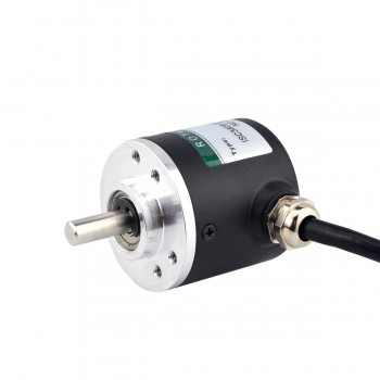
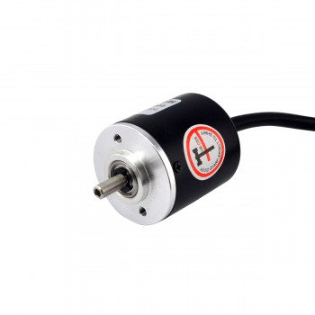
Un codificador de motor paso a paso es un dispositivo utilizado para detectar y controlar la posición angular y la velocidad de un motor paso a paso. El codificador generalmente consta de un dispositivo fotoeléctrico y un disco de codificación. Hay muchos espacios o agujeros iguales en el disco de codificación. La posición angular o la velocidad de rotación se determina en función de la oclusión de luz detectada por el dispositivo fotoeléctrico. Los codificadores de motores paso a paso pueden mejorar la precisión de posicionamiento de los motores paso a paso y evitar que pierdan pasos. Se utilizan ampliamente en algunos campos de control de precisión, como equipos médicos, equipos de semiconductores, máquinas herramienta de precisión, etc.
2.Funciones del codificador de motor paso a paso
1.Verificación de posición: a través de la retroalimentación del codificador, se puede verificar si la posición real del motor paso a paso alcanza la posición objetivo esperada. Si los recuentos del codificador no coinciden con la posición real del motor, se puede calcular y ejecutar un movimiento correctivo o un perfil de movimiento para garantizar la precisión del movimiento del motor.
2.Detección de bloqueo: el codificador puede comparar continuamente el recuento del codificador y el registro de posición del motor objetivo, en lugar de simplemente comparar al final del movimiento. Esta comparación continua puede detectar inmediatamente cuando un motor se cala, notificando al sistema eliminando así la incertidumbre de si el motor ha alcanzado su posición objetivo.
3.Realice un control de retroalimentación de circuito cerrado: la retroalimentación del codificador se puede combinar con el método de programación del controlador para crear un servosistema de circuito cerrado, evitando que el motor se detenga y creando un servosistema de circuito cerrado. Esto ayuda a mejorar la estabilidad y confiabilidad del sistema, especialmente en aplicaciones que requieren control de alta precisión.
3.Clasificación de codificadores de motores paso a paso
1.Codificador incremental: este tipo de codificador convierte la información de desplazamiento cuando el equipo se mueve en una señal de pulso continuo. El número de pulsos representa la cantidad de desplazamiento. Los codificadores incrementales solo emiten señales cuando el dispositivo está en movimiento. Estas señales generalmente se dividen en dos conjuntos de canales de salida, canal A y canal B, y hay una diferencia de fase de 90° entre los dos conjuntos de señales. La recopilación de estos dos conjuntos de señales al mismo tiempo puede determinar la dirección del movimiento del dispositivo. Las ventajas de los codificadores incrementales son un principio y una estructura simples, una larga vida mecánica promedio, una gran capacidad antiinterferente, una alta confiabilidad y son adecuados para transmisiones a larga distancia. Sin embargo, su desventaja es que no puede generar la información de ubicación absoluta del dispositivo.
2.Codificador absoluto: el codificador rotatorio absoluto convierte la información de desplazamiento cuando el dispositivo se mueve en cantidades digitales y la genera directamente a través de codificación binaria. En comparación con los codificadores incrementales, el disco de código de un codificador absoluto utiliza una serie de ranuras de cables opacas y transmisoras de luz para formar un conjunto de códigos binarios. Estos códigos binarios corresponden a cada posición del eje del codificador. La característica del codificador absoluto es que puede leer un código digital fijo en cualquier posición del eje giratorio. Este código digital corresponde directamente a la posición, por lo que no es necesario un contador. La ventaja del codificador absoluto es que puede leer directamente la posición absoluta del dispositivo sin necesidad de cálculos acumulativos, pero su desventaja es que la estructura es relativamente compleja y el costo es alto.
4.Seleccione las condiciones apropiadas del codificador del motor paso a paso
1.Escenarios de aplicación y requisitos de precisión: diferentes escenarios de aplicación tienen diferentes requisitos de precisión para los codificadores. Por ejemplo, las máquinas herramienta de alta precisión requieren codificadores de alta resolución para garantizar la precisión del procesamiento, mientras que los sistemas de transmisión generales pueden elegir codificadores de precisión media para reducir costos. Por lo tanto, primero es necesario determinar el nivel de precisión requerido según el escenario de aplicación específico.
2.Adaptabilidad ambiental: el codificador debe funcionar de manera estable en diversos entornos hostiles, por lo que se deben considerar su nivel de protección, rango de temperatura, resistencia a los golpes y otros factores. Elegir un codificador con excelente adaptabilidad ambiental puede reducir las tasas de falla y mejorar la eficiencia de la producción.
3.Protocolo de interfaz y comunicación: la señal de salida del codificador debe ser compatible con el sistema de control, por lo que es necesario elegir una interfaz y un protocolo de comunicación que cumplan con los estándares. Los codificadores con funciones de comunicación inteligentes pueden proporcionar más información de estado y funciones de diagnóstico para facilitar la resolución de problemas y el mantenimiento.
4.Tipos de codificadores de motor paso a paso: los codificadores de motor paso a paso se dividen en codificadores ópticos y codificadores electromagnéticos. Los codificadores ópticos tienen alta resolución y precisión, pero pueden verse afectados por el polvo, la grasa y otros contaminantes; los codificadores electromagnéticos son más duraderos y resistentes a los contaminantes, pero tienen una resolución y precisión ligeramente inferiores. Seleccione el tipo de codificador adecuado según los requisitos específicos de la aplicación, como precisión, resolución, costo e interferencia.
5.Fiabilidad y durabilidad: en un entorno de producción industrial, los codificadores deben soportar condiciones duras como altas temperaturas, alta humedad, vibraciones, etc. Por lo tanto, elegir una marca de codificadores con buena reputación y tecnología madura proporcionará una estabilidad estable para la producción. Asegurar.
En resumen, elegir un codificador de motor paso a paso adecuado requiere una consideración exhaustiva de factores como escenarios de aplicación, requisitos de precisión, adaptabilidad ambiental, protocolos de interfaz y comunicación, y tipo y marca de codificador. Al aclarar estos puntos, puede tomar decisiones más inteligentes para garantizar que el codificador pueda satisfacer las necesidades de un funcionamiento estable a largo plazo y, al mismo tiempo, mejorar la eficiencia de la producción y la calidad del producto.
1.Definición de servomotor
Un servomotor es un tipo especial de motor que tiene la capacidad de controlar con precisión la posición, la velocidad y la aceleración. Se diferencia de los motores normales en que puede ajustar su propio estado de movimiento de acuerdo con la señal de control de entrada para lograr un control de posición preciso. Los servomotores suelen constar de tres partes principales: motor, sensor y controlador. El motor es responsable de la rotación, el sensor se utiliza para medir la posición actual y la velocidad del motor, y el controlador ajusta el estado de movimiento del motor en función de la información de retroalimentación del sensor. El principio de funcionamiento de un servomotor es monitorear continuamente la posición y velocidad del motor a través del controlador y ajustar la salida del motor de acuerdo con la posición y velocidad objetivo preestablecidas. El controlador calculará el error del motor basándose en la información de retroalimentación del sensor y ajustará el movimiento del motor a través de la señal de salida para reducir el error y acercarse gradualmente a la posición objetivo.
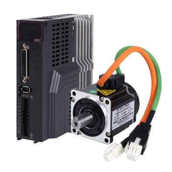
2.Principio de funcionamiento básico del servomotor.
1.Recibir señal de control: el servomotor primero recibe una señal eléctrica del sistema de control. Esta señal representa el desplazamiento angular o la velocidad angular deseada.
2.Procesamiento de señal: la señal recibida es procesada por el servocontrolador y convertida en instrucciones de control adecuadas para accionar el motor.
3.Conversión de energía: el servocontrolador convierte la señal procesada en energía eléctrica para hacer funcionar el servomotor.
4.Motor de accionamiento: El motor comienza a girar de acuerdo con las instrucciones recibidas, generando el desplazamiento angular o la velocidad angular correspondiente.
5.Sistema de retroalimentación: Los servomotores generalmente están equipados con dispositivos de retroalimentación (como codificadores) en su interior, que se utilizan para detectar la posición y velocidad reales del motor y enviar esta información al controlador.
6.Control de circuito cerrado: el controlador compara la información de retroalimentación con el valor esperado. Si hay una desviación, ajusta la salida del motor hasta alcanzar la posición y velocidad esperadas.
3.Ventajas de los servomotores
1.Control de alta precisión: el servomotor puede realizar un control de bucle cerrado de posición, velocidad y par, superar el problema del motor paso a paso fuera de sincronismo y mejorar la precisión de posicionamiento y la estabilidad del sistema.
2.Respuesta rápida: el servomotor tiene una velocidad de respuesta rápida y puede alcanzar la posición objetivo en poco tiempo. Es adecuado para ocasiones que requieren un posicionamiento rápido y un control preciso.
3.Alta respuesta dinámica: la tecnología avanzada de servocontrol proporciona una gran salida de par, lo que hace que el sistema tenga una respuesta dinámica extremadamente alta, superando con creces los límites de los sistemas paso a paso tradicionales.
4.Gran adaptabilidad: el servomotor tiene una gran adaptabilidad, puede soportar fluctuaciones de carga instantáneas y requisitos de arranque rápido y es adecuado para diversos entornos de trabajo complejos.
5Bajo ruido y bajo calor: en comparación con los motores normales, el calor y el ruido de los servomotores se reducen significativamente, lo que mejora la comodidad y confiabilidad del equipo.
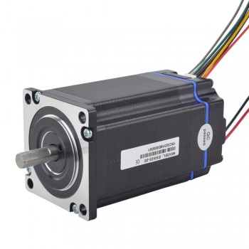
4.Escenarios de aplicación de servomotores.
1.Automatización industrial: los servomotores desempeñan un papel vital en el campo de la automatización industrial. Se utilizan ampliamente en brazos robóticos, transportadores, líneas de montaje y otros equipos para lograr procesos de producción eficientes y mejorar la eficiencia de la producción y la calidad del producto mediante un control preciso de la posición y el control del movimiento. La respuesta rápida y las capacidades de retroalimentación de posición precisa del servomotor le permiten adaptarse a entornos industriales complejos y requisitos de tareas.
2.Equipos mecánicos: Los servomotores también se utilizan ampliamente en diversos equipos mecánicos, como máquinas herramienta CNC, equipos de impresión, maquinaria de embalaje, etc. Proporcionan un rendimiento de trabajo de alta velocidad y alta precisión y satisfacen las necesidades de la fabricación moderna en cuanto a automatización e inteligencia de equipos.
3.Robótica: Los servomotores son ideales para el accionamiento de articulaciones de robots. Pueden proporcionar una potencia de salida de alto rendimiento y un control de movimiento flexible para satisfacer las diferentes necesidades de los robots en diversas industrias, servicios y entornos especiales. En campos como las líneas de producción automatizadas, la logística y el almacenamiento, los robots accionados por servomotores pueden lograr operaciones eficientes y tareas de automatización.
4.Equipo médico: En la industria médica, los servomotores se utilizan en equipos de imágenes médicas, robots quirúrgicos y otros equipos. Tienen las características de un control preciso y garantizan un diagnóstico preciso y un funcionamiento quirúrgico de los equipos médicos.
5.Aeroespacial: Los servomotores desempeñan un papel vital en equipos aeroespaciales como aviones, misiles y satélites, logrando funciones precisas de control de vuelo y navegación y garantizando la seguridad y estabilidad de la aeronave.
Además de los campos de aplicación anteriores, los servomotores también se utilizan ampliamente en diversos campos, como equipos electrónicos, fabricación de automóviles y maquinaria textil. Con el avance continuo de la ciencia y la tecnología, los servomotores también mejoran y se desarrollan constantemente, desarrollándose gradualmente hacia una mayor precisión, una velocidad de respuesta más rápida y campos de aplicación más amplios.
1.What is a hollow shaft stepper motor?
The hollow shaft stepper motor is a special kind of stepper motor. Its internal structure adopts a hollow design and is mainly composed of magnets, inner and outer frames, bearings, coils and other parts. This kind of motor has the advantages of high power density, small size, high efficiency, low noise, low temperature rise and high reliability, so it has important applications in aerospace, military, automobile, medical, robotics and other fields. . The design of the hollow shaft stepper motor greatly optimizes the mechanical design, facilitates wiring, and saves design space and production costs.
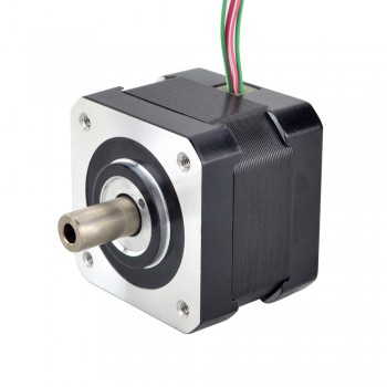
2.How to reduce the temperature of hollow shaft stepper motor
1.Fan cooling method: Install a fan on the stepper motor, and use the fan to circulate the air around the motor to accelerate the dissipation of heat to achieve the purpose of heat dissipation. This method is simple and effective, and can significantly reduce the temperature of the motor.
2.Heat sink cooling method: Install a heat sink on the surface of the stepper motor, and transfer the heat inside the motor to the outside through the heat sink to accelerate the dissipation of heat, thereby achieving the purpose of heat dissipation. The heat sink can effectively conduct heat from the inside of the motor to the outside, helping the motor to cool down.
3.Liquid cooling method: Set up a liquid cooling system inside the stepper motor to transfer the heat inside the motor to the outside through the liquid to accelerate the dissipation of heat to achieve the purpose of heat dissipation. The liquid cooling system can absorb and dissipate the heat generated by the generator more effectively, and is suitable for application scenarios with high temperature control requirements.
4.Reducing current method: By reducing the driving current of the stepper motor, the heat generated by the motor is reduced to achieve the purpose of heat dissipation. Reducing the current can reduce the loss and heat of the motor, thereby lowering the motor temperature.
3.Application areas of hollow shaft stepper motors
1.In the field of automation equipment, hollow shaft stepper motors are widely used in robots, automated production lines, CNC machine tools, etc. to provide precise position control and motion control while facilitating the passage of cables, air pipes, etc.
2.In terms of medical equipment, hollow shaft stepper motors are often used in surgical robots, medical imaging equipment, laboratory automation equipment, etc., to meet the requirements of high precision and reliability, and to facilitate the layout of cables, trachea, etc.
3.In printing equipment, hollow shaft stepper motors are used to drive printing rollers, paper conveying and other components to improve the integration and reliability of the equipment.
4.In the field of textile machinery, hollow shaft stepper motors are used to drive components such as yarn winding and looms, and also improve the integration and reliability of the equipment.
5.In terms of stage equipment, hollow shaft stepper motors are used to drive stage lifting, rotation and other components to improve the integration and reliability of the equipment.
6.In the field of aerospace, hollow shaft stepper motors are used to drive components such as rudder surfaces and landing gear to facilitate the passage of cables, air pipes, etc., and improve the integration and reliability of equipment.
7.In vehicle engineering, hollow shaft stepper motors are used to drive power windows, seat adjustments and other components to facilitate the passage of cables, air pipes, etc., and improve the integration and reliability of equipment.
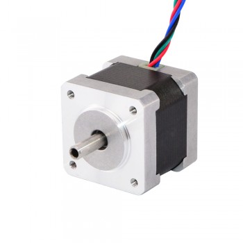
4.Design features of hollow shaft stepper motors
1.Energy-saving characteristics: The energy conversion efficiency of hollow shaft motors is very high. The maximum efficiency is generally above 70%, and some products can reach above 90%. Compared with iron core motors, they have higher energy utilization.
2.Control characteristics: rapid starting and braking, extremely fast response, the mechanical time constant is less than 28 milliseconds, and some products can reach within 10 milliseconds, which makes it easy to adjust the speed under high-speed operation within the recommended operating area. Sensitive adjustment.
3.Drag characteristics: The operation stability is very reliable, and the fluctuation of the rotation speed is very small. As a micro motor, the fluctuation of the rotation speed can be easily controlled within 2%, ensuring the smooth operation.
4.High power density: Due to its compact structure, the hollow stepper motor is smaller in size, which can save space and thus improve energy utilization.
5.High efficiency: The hollow design can reduce the weight of the motor and increase the space of the magnetic circuit, thereby increasing the power density of the motor.
6.Low noise: The noise of the hollow stepper motor is much smaller than that of the traditional stepper motor, which can better protect the environment.
7.Low temperature rise: The temperature rise of the hollow stepper motor is lower than that of the traditional stepper motor, which can better ensure the service life of the motor and better meet the needs of users.
8.High reliability: The reliability and stability of hollow stepper motors are much higher than traditional stepper motors, and they are suitable for applications that require high reliability and stability.
9.Hollow structure: The center of the motor shaft has a hollow hole, allowing materials, signals, light, etc. to be transmitted through the axial space. This design can achieve a more compact and optimized layout in machine design.
1.What is a Right Angle Planetary Gearbox
A right angle planetary gearbox, also known as a bevel gearbox, is a gearbox that changes the direction of the rotating shaft by 90 degrees. It is a compact and efficient gear reducer that combines the advantages of right angle gearboxes and planetary gearbox mechanisms. Most right angle gearboxes operate at a 90 degree angle between the input and output. Depending on how the right angle gearbox or right angle planetary gearbox is constructed, shaft misalignment may occur. Right angle planetary gearboxes rely on the mechanism of planetary gearboxes. The basic structure of a planetary gearbox basically consists of a "sun gear" mounted in the center, an outer ring, planetary gears surrounding the sun gear, and a carrier.
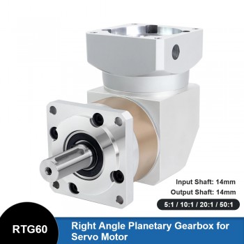
2.Structure of a Right Angle Planetary Gearbox
It mainly consists of a sun gear, a ring gear, a planet carrier, and several planetary gears supported on the planet carrier. This structure is a type of planetary gear system in which the sun gear, the ring gear, and the planet carrier have a common fixed axis. The planetary gears are supported on the planetary gear shaft fixed to the planet carrier, and mesh with the sun gear and the ring gear at the same time. This structure can achieve a variety of gear combinations, including low gear, medium gear, high gear (overdrive) and reverse gear, by adjusting the active and passive states of the sun gear, planetary carrier and ring gear. When all moving parts are unconstrained, the transmission is in neutral state
3.Working principle of right-angle planetary gearbox
Mainly involves the combination of input shaft, output shaft and planetary gear. The characteristic of this gearbox is that the input shaft and output shaft are arranged at right angles, and the planetary gears are connected through the inner ring gear and the outer ring gear. When working, the input shaft provides power input through the motor or other power source to rotate the inner ring gear. The inner ring gear drives the planetary gear, and the meshing between the planetary gear and the inner ring gear and the outer ring gear realizes power transmission and direction change, and finally outputs power through the output shaft. This structure makes the right-angle planetary gearbox have a compact structural design, which can achieve efficient power transmission in a limited space, and has the characteristics of high transmission efficiency (generally more than 90%), strong load-bearing capacity, smooth operation, low noise, and long service life. In addition, the reversing speed is fast and the precision is high, which is suitable for application environments with high steering precision requirements
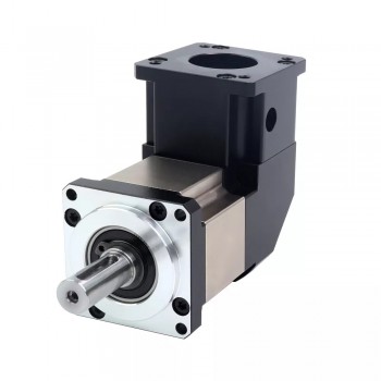
4.Characteristics of right-angle planetary gearbox
1.Small size, light weight, and compact structure: Due to the design optimization of the planetary gearbox, its volume and weight are relatively small, while maintaining the compactness of the structure, which is suitable for application scenarios with limited space.
2.Strong load-bearing capacity: The design of the planetary gearbox allows it to have a high load-bearing capacity, can withstand large forces and torques, and is suitable for applications requiring high loads.
3.High drive efficiency: The symmetry and reasonable power distribution of the planetary gear system make the drive efficiency high, which can effectively convert power and reduce energy loss.
4.Able to achieve complex movements: By properly selecting the type and distribution scheme of the planetary gearbox, it is possible to achieve synthetic and decomposed movements to meet various complex movement requirements.
5.Good stability: The planetary gears use the same planetary wheels and center wheels for uniform distribution, which ensures the stability of the movement. At the same time, they have good impact resistance and vibration resistance, and work more reliably.
5.Specific application areas of right-angle planetary gearboxes
1.In industrial production lines, right-angle planetary gearboxes are widely used in conveying equipment, mixing equipment, lifting equipment, etc. These equipment play a vital role in the production process and ensure the smooth progress of the production process.
2.In terms of machine tool equipment, right-angle planetary gearboxes are used for the transmission of mechanical equipment such as CNC machine tools, lathes, and milling machines, which improves processing accuracy and efficiency.
3.In the field of automation equipment, right-angle planetary gearboxes are used for the transmission of automated production equipment such as robots, automatic assembly lines, and packaging equipment, which promotes the development of automated production.
4.In the field of transportation, right-angle planetary gearboxes are used in the transmission systems of electric vehicles, electric vehicles and other transportation vehicles, improving the performance and efficiency of transportation vehicles.
